2 Humbucker Guitar
Custom Wiring III
Updated April, 2015
Scroll to the bottom for alternative circuits
that have no dead spots.
| |
When you have a two humbucker guitar (with each humbucker having 4 conductor wiring), the amount of modifications that can be done and the tones that can be produced are enormous. Heck, this is the third two humbucker "mod" on this website. (the other two are Funky Five Switching and Super Seven Switching).
This modification is usually referred to as the "Jimmy Page Wiring" and it does offer a great variety of tones.
 If you use push-pull potentiometers or "pots" (as shown above), then this wiring will not affect the appearance of your guitar whatsoever. Basically, a push-pull pot is a "pot" with a switch attached to it (almost always a DPDT switch).
It is switched by pushing down on the knob which is attached to the shaft of a volume or tone control.
If you use push-pull potentiometers or "pots" (as shown above), then this wiring will not affect the appearance of your guitar whatsoever. Basically, a push-pull pot is a "pot" with a switch attached to it (almost always a DPDT switch).
It is switched by pushing down on the knob which is attached to the shaft of a volume or tone control.
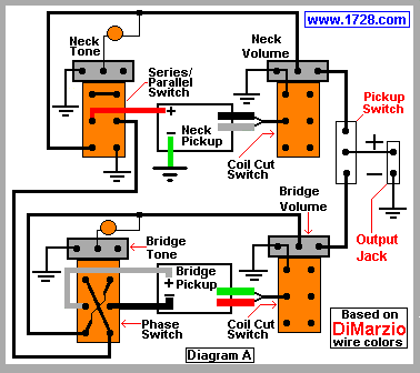
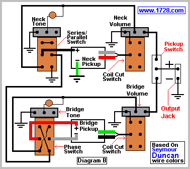
There are dozens of drawings that can be found on the Internet for this type of wiring but we think ours is probably the most concise and easiest to follow. Actually, you get two diagrams - one for DiMarzio pickup wire colors and the other for Seymour Duncan wire colors.
Before You Begin
One disadvantage of these circuits (Diagrams A and B) is that when the series / parallel switch is set to "series", if the pickup switch is in the neck position or if it gets switched to the neck position, the result will be no sound at all.
However, if you scroll to the bottom of the page you will see a diagram for a circuit with no dead spots.
As we've said many times, doing any unauthorized work on your guitar will void the warranty.
If your guitar has two 2 wire humbuckers, then you must convert both of these to 4 wire humbuckers. If they can't be converted into 4 wire pickups then you must buy two new pickups, making sure that the new pickups are both 4 wire humbuckers. You should keep this extra work or extra expense in mind before starting, as it will probably be the major factor affecting whether or not you want to attempt this project.
Unlike all the other circuits on this website, this requires the use of 4 DPDT push pull "pots", which means that you'll be replacing all 4 pots already in your guitar and substituting each with a push pull "pot". You must take this extra wiring, soldering and time into consideration before starting this project.
Another concern is
the cost of the modification which is going to be somewhat higher than the other rewirings found on this website. Making a very rough estimate, the cost of one DPDT push-pull pot is about $10 and so the parts will cost about $40. You could try getting a deal at your local guitar shop or ordering this as a "kit" from an online guitar part supplier. These kits usually consist of 4 DPDT push pull pots and sometimes things you don't need such as a pickup switch, an output jack, and 2 capacitors, all of which should already be in your guitar.
Be careful when ordering because some online companies sell "kits" of this wiring consisting of just one DPDT push pull pot and 3 regular "pots". You need switches on all four "pots".
If you don't want the extra work or expense of replacing all four volume and tone controls, there is a much simpler alternative. You can drill four holes in your guitar and use toggle switches instead. You'd need 2 DPDT and 2 SPST switches and nothing else. Of course it is your guitar and you have to decide if you want 4 additional holes drilled into it.
If your guitar is very thin (such as a Gibson SG), there is not enough room for a push pull "pot" to fit in. Remember that the DPDT switch on the push pull "pot" will take up extra room.
If you are installing this in a Les Paul, you will need long shaft push pull "pots".
About The Circuit
This circuit will produce 21 different tones, ten of which are hum-canceling (see the chart below). You may have noticed from the wiring diagram at the top of this page that the bridge pickup has an alternate (or what I call an "inside-out") wiring which allows hum-canceling to occur whenever both single coils are chosen. To find out why this occurs, go to this page.
Whenever you see **** in the chart below, it means that switch's position has no effect on the resulting tone.
There are some additional modifications you can make.
The coil cut switches only utilize 2 of the 6 terminals on each push pull pot.
You could make just one push pull pot control the coil cut for both pickups. (see diagram at left)
(Incidentally, a series link is the junction formed by connecting the "middle" 2 wires of a humbucking pickup).
With the coil cut function for both pickups combined on one switch, you'd only need 3 push pull pots.
If you chose to use toggle switches for this project, it would mean one less hole to be drilled into the guitar.
The disadvantage of this is that you will lose the last 8 tones in the chart below. Maybe you really didn't want these single coil combined with humbucker sounds, but they will be lost if you choose to go with 3 switches instead of all four.
|
| Pickup
Switch | S/P
Switch | Phase
Switch | Neck
Coil
Cut
Switch |
Bridge
Coil
Cut
Switch | Result (HC means hum-canceling) |
| NeckOnly | **** | **** | Down | **** | Neck Humbucker Only - HC |
| Neck Only | **** | **** | Up | **** | Coil A Only |
| Bridge Only | **** | **** | **** | Down | Bridge Humbucker Only - HC |
| Bridge Only | **** | Down | **** | Up | Coil D Only |
Bridge Only | **** | Up | **** | Up |
Coil C Only |
| Both | Down | Down | Down | Down |
Neck & Bridge In Parallel In Phase - HC |
| Both | Up | Down | Down | Down |
Neck & Bridge In Series In Phase - HC |
| Both | Down | Up | Down | Down |
Neck&Bridge In Parallel Out Of Phase-HC |
| Both | Up | Up | Down | Down |
Neck&Bridge In Series Out Of Phase-HC |
| Both | Down | Down | Up | Up |
Coil A & Coil D In Parallel In Phase - HC |
| Both | Up | Down | Up | Up |
Coil A & Coil D In Series In Phase - HC |
| Both | Down | Up | Up | Up |
Coil A&Coil C In Parallel Out Of Phase-HC |
| Both | Up | Up | Up | Up |
Coil A&Coil C In Series Out Of Phase-HC |
| Both | Down | Down | Up |
Down | Coil A & Bridge In Parallel In Phase |
| Both | Up | Down | Up | Down
| Coil A & Bridge In Series In Phase |
| Both | Down | Up | Up | Down
| Coil A & Bridge In Parallel Out Of Phase |
| Both | Up | Up | Up | Down
| Coil A & Bridge In Series Out Of Phase |
| Both | Down | Down | Down |
Up | Neck & Coil D In Parallel In Phase |
| Both | Up | Down | Down |
Up | Neck & Coil D In Series In Phase |
| Both | Down | Up | Down | Up
| Neck & Coil C In Parallel Out Of Phase |
| Both | Up | Up | Down | Up
| Neck & Coil C In Series Out Of Phase |
Alternative Circuits
The circuits shown here (Diagrams C & D) have no dead spots whatsoever.
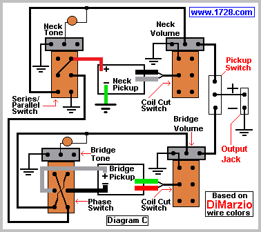
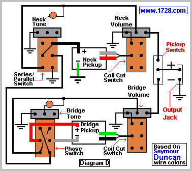
This circuit works pretty much the same as the previous ones except that when it is switched for "series", the pickup switch acts as follows:
| Pickup Switch | Result |
Neck Only | Neck Only |
Middle | Neck Only |
Bridge Only | Both Pickups In Series |
Good luck with the wiring.
Go to Series Parallel Master Switch
Return To Guitar Page One
Copyright © 1728 Software Systems
Return To Home Page
|